Go to Link Optimization → Wireless, set the Bandwidth to 40 MHz, and click Apply to save the changes.
-
-
Application Notes
-
-
Introduction
Starlink, a satellite internet constellation operated by SpaceX, aims to provide high-speed internet access across the globe, especially in remote and underserved areas. Utilizing a vast network of low Earth orbit (LEO) satellites, Starlink endeavors to bridge the digital divide, offering users seamless connectivity that rivals traditional broadband services.
On the other hand, Doodle Labs' Mesh Rider radios represent a significant advancement in wireless communication technology. Designed for robust performance in challenging environments, Mesh Rider radios utilize a mesh networking approach to ensure reliable, secure, and scalable communication solutions. These radios are particularly valuable in industrial, defense, and unmanned system applications, where traditional communication methods fall short. 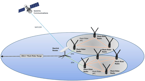
Fig. 1 Starlink + Mesh Rider Integration Diagram
Together, Starlink and Doodle Labs' Mesh Rider radios exemplify the forefront of innovative technologies aimed at enhancing connectivity and communication across various sectors and geographical landscapes. Mesh Rider Radios can extend Starlink SATCOM connections to base stations in up to a 20km radius, for applications in disaster emergency communications, denied environments or rural environments.
Starlink Initial Setup
2. Download the Starlink Mobile Application (Android and Apple iOS)
a. Android OS: Starlink Google Play Store
b. Apple iOS: Starlink Apple App Store
3. Setup Starlink w/ Mobile Device, Reference Link: Starlink Standard Setup Guide
a. Install the cables for the Starlink ‘Dishy’ + Router
b. Ensure a clear line of sight in the Starlink App
c. Connect and align the Starlink “Dishy”
d. Connect to Starlink over Wi-Fi

Fig. 2 Successful Connection in the Starlink Mobile App
Mesh Rider to Starlink Setup ➡️ Ethernet to Router
For connecting a Mesh Rider Radio (regardless of if Wearable, OEM, mini or nano, etc.) to the Starlink Gen03 Router the setup will be the same. Note the Wearable radio does not require an eval-kit for the RJ-45.
The Starlink Dishy will connect to the far left RJ-45 Power over Ethernet (POE), the second and third middle RJ-45 ports will be used to connect to a radio over ethernet and the far-right port will be utilized to supply power to the Starlink Gen 03 Router (57V 3.42A) with the Starlink charging block.
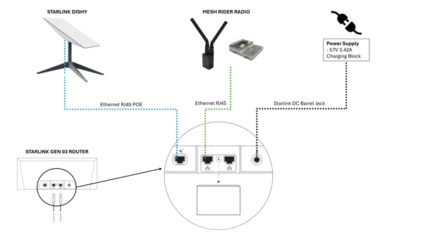
Fig. 3 Connecting a Radio to the Starlink Router
Wearable Mesh Rider Radio Setup:
The power supply for the Wearable radio can be the a) Battery Power Supply or b) 6-24V DC through the PWR+USB_D port.
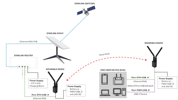
Fig. 4 Wearable Radio + Starlink Hardware Integration
OEM, Mini-OEM and Nano-OEM Setup:
Reference Eval Kit Connector Descriptions:
• Nano-OEM : nano-OEM and Helix Mesh Rider Radio – Eval Kit Connector Descriptions
• OEM : Multiband-OEM User Guide (OEM Form Factor)
On the Starlink Router side simply connect the ethernet RJ-45 port of the Starlink router => Eval Kit RJ-45 Ethernet port.
The power supply for the OEM, Mini-OEM or Nano-OEM is 5V DC through the eval-kit DC Barrel Jack.
The OEM, Mini-OEM and/or Nano-OEM radio can be connected to an End User Device (EUD) such as a Tablet, PC, Laptop, etc. This connection can occur through ETH over the RJ-45 Ethernet port and through USB via the USB-C Device port (top-left eval-kit) or the USB-A Device port (bottom-right Mini-OEM), as in Fig. 5 below.
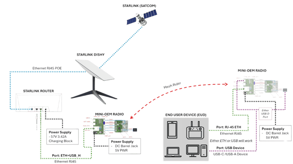
Fig. 5 Mini-OEM Radio + Starlink Hardware Integration
Networking + IP Addressing
192.168.1.x subnet, generally where 192.168.1.23 is the first radio connected and 192.168.1.24 is the second radio connected. These addresses will depend on the number of, and order of devices connected. 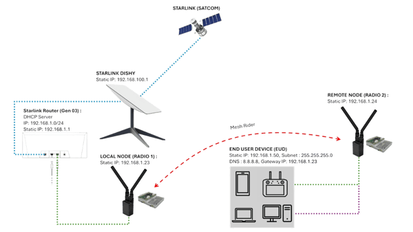
Fig. 6 Example Networking and IP Addressing for a Mesh Rider + Starlink Integration

Fig. 7 Starlink App Network Main Router
Local Node:
“smartradio-301a505d95”, we can view the IP of this radio is now 192.168.1.23 on the Starlink DHCP server as noted in Fig. 8 below. Note if you are confused on the Local Node, you can power off the Remote Node and the single radio connected to the Starlink Router (and it’s IP Address) will be the Local Node.

Fig. 8 Clicking on “smartradio-xxx” Interface to Find Local Node IP
Remote Node:
“smartradio-301a3a12c5” in the Starlink App, we can see the IP of this radio is now 192.168.1.24 on the Starlink DHCP server. See Fig.9 below. 
Fig. 9 Clicking on “smartradio-xxx” Interface to Find Remote Node IP
End User Device (EUD):
192.168.1.x /24 subnet. It is further optimal to set the EUD Gateway IP Address to that of the Local Node static IP Address. When wanting to use the Starlink based Internet Service Provider (ISP) access to internet it, on the EUD configure the network infrastructure to use Google Public DNS addresses, such as 8.8.8.8, for their clients.
Example EUD IP Routing:
• Subnet Mask: 255.255.255.0
• Gateway IP: 192.168.1.23
• DNS : 8.8.8.8

Fig. 10 Example EUD Network Setup (Windows 11)
Network Testing:
sean@doodle: ping google.com

Fig. 12 Ping Testing Google from the EUD
sean@doodle: sudo apt install speedtest-cli

sean@doodle: speedtest --secure

Fig. 12 Speed Testing Internet (ISP) Throughput from the EUD
High-Throughput Optimizations:
‘simpleconfig’. If you do not require an ISP or internet access for your application this throughput may be appropriate. However, most common web browsers i.e. Google Chrome require a minimum of 2-5 Mbps for consistent use, such that these High-Throughput Optimizations may be required to achieve 20+ Mbps.
GUI Based High-Throughput Settings:
192.168.1.23 and Remote Node IP Address: 192.168.1.24, where these would be used in two different web browser windows. Go to Advanced ==> Network Configuration ==> Traffic Prioritization and uncheck the following: Optimize for Robustness, Optimize for Latency, Enable Automatic C&C
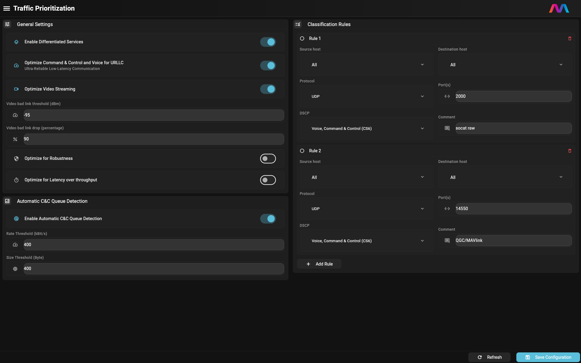
Fig. 13 Uncheck Robustness, Latency and Automatic C&C Que

Fig. 14 Uncheck Enable Differentiated Services:
CLI Based High-Throughput Settings:
192.168.1.23 and Remote Node: 192.168.1.24.
CLI for Local Node:
sean@doodle: ssh root@192.168.1.23

root@smartradio-301a505d95:~#
    uci set diffserv.@general[0].diversity_rates='0'
    uci set diffserv.@general[0].low_latency='0'
    uci set diffserv.@qdetection[0].qdetection_enabled='0'
    uci set diffserv.@general[0].enabled='0'
    uci commit
    /etc/init.d/diffserv restart
    wifi
CLI for Remote Node:
sean@doodle: ssh root@192.168.1.24

root@smartradio-301a505d95:~#
    uci set diffserv.@general[0].diversity_rates='0'
    uci set diffserv.@general[0].low_latency='0'
    uci set diffserv.@qdetection[0].qdetection_enabled='0'
    uci set diffserv.@general[0].enabled='0'
    uci commit
    /etc/init.d/diffserv restart
    wifi
High-Throughput Setting Network Testing:
sean@doodle: speedtest --secure

Fig. 15 Speed Testing High-Throughput Settings from the EUD
GUI Based High-Bandwidth Settings:
In the Graphic User Interface (GUI) on both the Local Node (Radio 1) and Remote Node (Radio 2) , required to change to the same bandwidth on both nodes or nodes will not connect. In this example, Local Node IP Address:
192.168.1.23 and Remote Node IP Address: 192.168.1.24 , where these would be used in two different web browser windows.  Fig. 16 Change the Radio’s (i.e. wlan0) Bandwidth to 40MHz
CLI Based High-Bandwidth Settings:
192.168.1.23 and Remote Node: 192.168.1.24 .
CLI for Local Node:
sean@doodle: ssh root@192.168.1.23

root@smartradio-301a505d95:~#
    uci set wireless.radio0.htmode='HT40'
    uci set wireless.radio0.chanbw='40'
    uci commit
    wifi
CLI for Remote Node:
sean@doodle: ssh root@192.168.1.24

root@smartradio-301a505d95:~#
    uci set wireless.radio0.htmode='HT40'
    uci set wireless.radio0.chanbw='40'
    uci commit
    wifi
High-Throughput + High-Bandwidth Network Testing:
sean@doodle: speedtest --secure
 Fig. 17 Speed Testing High-Throughput + High-Bandwidth Settings from the EUD
Unlicensed vs. Licensed Frequency Performance:
sean@doodle: speedtest --secure
 Fig. 18 Speed Testing Unlicensed Frequency (i.e. 2.25GHz)
Mesh Rider to Starlink Setup ➡️ Wearable or OEM Wi-Fi to Router
“DoodleSATCOM”. Note: Wi-Fi Client access to the Starlink Router will not work with the Mini- or Nano-OEM who do not have a secondary Wi-Fi radio (wlan1) that the Wearable and OEM radio have.
 Fig. 19 Wearable Radio Wi-Fi + Starlink Hardware Integration
Local Node Setup with the EUD Hotspot Wizard:
“DoodleSATCOM”. For more information on the EUD Wizard check out the GCS Profile and EUD Wizard Guide.
In the GUI, navigate to Utilities → EUD Wizard, then scroll to the Hotspot Configuration section. Enable the following options:
-
- Enable Hotspot Wizard
-
- Network Discovery Mode (this enables scanning for available Wi-Fi networks)
Once enabled, available hotspots will automatically populate on the right side of the screen under Network Discovery. Click the Refresh icon if needed to initiate a new scan, and select Connect next to your desired network. Finally, click Save Configuration to apply the changes.
 Fig. 20 Setup EUD Hotspot Wizard
“DoodleLabsWIFI”) and then click connect. Fig. 21 EUD Hotspot Wizard Scan for Starlink Network Name
Wi-Fi Networking + IP Addressing
10.223.x.y/16 to 10.x.y.1/8 . In our example the Local Nodes original address was 10.223.93.149 and after the EUD Wizard is now 10.93.149.1 . If the application required an EUD on the Local Node topology, this would look like Fig. 24 and the EUD would have example IP Addressing found in Fig. 25 below.  Fig. 24 Starlink Wi-Fi Connection to Radio + EUD
Fig. 25 Example Wi-Fi EUD Network Setup (Windows 11)
Other Advanced Wi-Fi Network Topologies:
Fig. 26 Example Wi-Fi => Mesh Rider => Wired Network
Starlink => Wi-Fi => Local Node => Mesh Rider (RF) => Remote Node => Wi-Fi => EUD
Fig. 27 Example Wi-Fi => Mesh Rider => Wi-Fi Network
Wi-Fi Throughput Optimizations:
CLI Wi-Fi Based High-Bandwidth Settings:
10.93.149.1 and Remote Node: IP Address will vary based on network setup. However, Remote Node (if required) will have the same uci commands below as for the Local Node
CLI for Local Node:
root@doodle: ssh root@10.93.149.1

root@smartradio-301a505d95:~#
    uci set wireless.radio1.htmode='HT40'
    uci set wireless.radio1.chanbw='40'
    uci commit
    wifi
Wi-Fi Network Testing:
sean@doodle: speedtest --secure
 Fig. 29 Speed Testing Wi-Fi High-Throughput + High-Bandwidth Settings from the EUD


