
Introduction
This guide provides step-by-step instructions to integrate the Doodle Labs Mesh Rider Radio with QGroundControl (QGC) and flight controllers running PX4 autopilot firmware. It covers essential configurations for transmitting MAV Link telemetry.

Fig. 1 System Setup
System Setup
The Mesh Rider Radio uses a customized Openwrt with Doodle Labs Mesh Rider® enhancements for low-latency control and high-throughput video, ideal for UAVs and robotics. This guide helps programmers configure the Mesh Rider Radio Serial interface, relaying IP-based wireless communications to the serial interface, with examples for data transmission between radios or directly over the network. Figure 1 shows the basic system setup between the UAV and the Ground Control Station.
UAV Hardware Setup
Doodle Labs currently offers four main hardware variants in its Mesh Rider Radio lineup. UART is available on all current variants. However, these hardware variants have different pinouts, and you should refer to the documentation package of your specific hardware for pinout information. The hardware versions can be differentiated by the model number. In all cases, the UART is implemented as one TX line, one RX line, and GND.
Please note that - 1. The legacy models (-2H-*U) have a USB host port on the auxiliary connector and have no UART port. For the UART port, you require -2H-*S model.
Connection Guide
- 1. The UART connector is a 3-pin connector consisting of TX, RX, and GND. The TX and RX wires should be coupled closely with the GND wire for good signal integrity.
- 2. Typically, when two devices are connected over UART, the TX wire of the first device should be connected to the RX wire of the other device and vice versa.
- 3. While most models use 3.3-V TTL signaling, the External Mesh Rider Radio (-2J-*E) uses RS232 signaling. Please consult the documentation package of your hardware before hooking up the UART.
Hardware Connection
By default, the Pixhawk 4 supports telemetry on serial ports TELEM1 and TELEM2. The Mesh Rider Radio UART pinout can be found in the Mesh Rider Radio Integration Guide. For details on how to setup a serial-to-serial bridge, please consult the Doodle Labs Technical Library.
Figure 2 shows the TELEM1 Pixhawk port to UART Mesh Rider Radio port wiring. UART_RX from the Mesh Rider Radio should be connected to MCU_TX on the Pixhawk 4, and UART_TX from the Mesh Rider Radio should be connected to MCU_RX on the Pixhawk 4. A ground connection is required to complete the loop. VCC_5V, MCU_RTS, and MCU_CTS can be left open.If you are facing issues in UART communication, also refer to our UART Debug Guide for troubleshooting steps.

Fig. 2 Mesh Rider Mini model UART to Pixhawk 4 TELEM1 wiring
Setup using the GUI
To begin setup, open a web browser and enter the IP address of the Mesh Rider Radio. From the left-hand menu, navigate to Utilities → Serial Config. This will open the Serial Configuration page, as shown in Fig. 3. To enable the serial bridge, toggle the switch at the top. The typical baud rate used by the PX4 flight controller is 57600, and the recommended device is /dev/uart0, unless an external serial adapter is connected. You can configure the role as either Unicast Server or Unicast Client. For client mode, use the IP address of the host running QGC, set transport to UDP, and port to 14550. In server mode, you may use any desired port and choose either TCP or UDP transport. After configuring your settings, click Save Configuration to apply the changes.

Fig. 3 Serial Configuration GUI
Recommended Settings
We recommend using UDP transport for Command & Control as it does not establish a connection between the server and client. In the event that the drone moves in and out of range, a TCP connection will experience higher latency and significantly higher reconnection time should the connection break.
Mesh Rider Radio Optimization
The following optimizations apply to both Mesh Rider Radio 1 and Mesh Rider Radio 2 in Figure 1.
The Mesh Rider Radio Configuration Guide includes a section on Common Network Settings which we suggest you review for details on how to configure the Mesh Rider Radio. We recommend:
● For the RM-2450, 2.4-GHz ISM band radio, do not use 20-MHz bandwidth, use 5/10/15 MHz bandwidths instead to avoid interference from Wi-Fi devices.
● Use the C&C and Voice queue for telemetry (MAVLink) data. In the example above, you would map port 3000 (or 14550) to the CS6 queue. Enable "Optimize Command & Control for Voice and URLLC".
● Use the Video queue for Video. Enable "Optimize Video Streaming".
GCS Hardware Setup
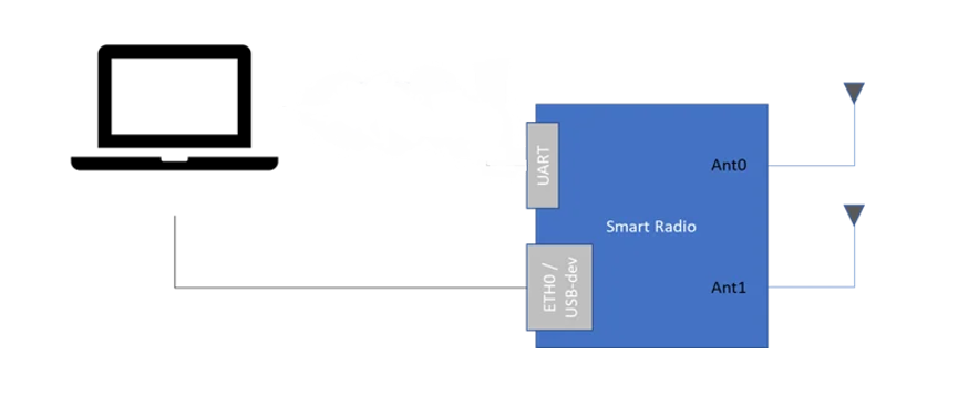
Fig. 4 Generic UART hardware connection
GCS Finder
(Note: GCS Finder and the serial configuration cannot be enabled at the same time)
If you are using a MAVLink-based Ground Control Station (GCS) such as QGroundControl or Mission Planner, you can use our built-in GCS-Finder utility. The connection diagram is assumed to be like that in Fig. 5. Please note you only need to run GCS finder on the radio that is directly connected to the flight controller.

Fig. 5 UAV GCS System
GCS finder works by sending sends broadcast packets to the subnet (Broadcast IP Address below). The packets contain the Source IP address and Source port. The GCS software such as QGC or Mission Planner should pick up the broadcast packets and use the information to connect to the flight controller using the Source IP address and source port. A screenshot is shown in Fig. 6. After enabling GCS Finder, the serial configuration will be disabled.

Fig. 6 GCS finder configuration
Corresponding Mission Planner Settings for the configuration in Figure 6.
UDP
Local port: 2000
Troubleshooting Serial Config/GCS Finder issues
1. Certain versions of the firmware the settings for GCS finder or serial config might not apply until a restart. Update to the latest firmware to ensure things work as expected.
2. Ensure the device running the GCS software is on the same subnet as the radio connected to the flight controller.
3. Check the radio's firewall ports. Sometimes after running simple config the firewall rules return to default.
4. Check your GCS computer firewall rules.
5. Sometimes power cycling the flight controller while it is connected to the radio might help achieve a connection in the QGC software.
Android Setup
There are three ways to connect an Android device to a Mesh Rider Radio:
1. USB Reverse Tethering: This option is typically available on Smart Tablets, where it is expected that they do not have a dedicated internet connection and are getting their interconnection from another device. In this mode, the Smart Tablet acts as DHCP client, or can be assigned a static IP address. The Smart Tablet's USB port is in "host" mode and supplies 5-V to a connected device. Please make sure that the tablet is able to supply about 15W of power on its USB-C port. This mode is only supported by the Wearable and Helix Mesh Rider Radio form factors and not the Embedded or External form factors.
2. Wi-Fi: The Wearable Mesh Rider Radio includes an auxiliary WiFi radio and this is the recommended way to connect an Android device to the Mesh Rider network.
3. USB Tethering: This option is available on most Smart Phones, In this mode, the Smart Phone starts a DHCP server at a fixed IP address. The Smart Phone's OTG port is in "device" mode and requires a 5-V input. Generally it is not possible to turn off the DHCP server or modify the IP address of the Smart Phone without rooting the device.
The recommended setup is shown in Figure 6. The Wearable Mesh Rider Radio runs a Wi-Fi AP which is bridged to the Mesh Rider network that the Tablet can connect to. The next best option is USB Reverse Tethering as it doesn't impose any limitations on the IP addressing. Make sure to choose a Tablet which supports USB Reverse Tethering.
Fig. 6 QGroundControl MAVLink Verification
Mav link Test
In QGroundControl, add a new Comm Link as shown in Figure 7. Change the host address (Server Address) to the IP address of the Mesh Rider Radio connected to the drone, and the network port to the listening port used by the Mesh Rider Radio. Click OK and then Connect.

Fig. 7 QGroundControl Setup
Linux/Windows
You can confirm the MAVLink connection is good by going to the tab shown in Figure 8, and verifying the MAVLink heartbeat shows 1.0Hz.

Fig. 8 QGroundControl MAVLink Verification
GCS Network Port Binding (Important)
Some GCS software (notably Mission Planner) do not allow the user to bind the socket to a particular network port when in client mode. Instead, the network port is assigned by the kernel. Therefore, every time Mission Planner restarts it's UDP client, it will restart from a new network port. Unfortunately, this confuses socat (on the Mesh Rider Radio), and it can lead to high MAVLink packet loss.
The suggested solution is to setup socat in client mode and input the IP address of the GCS. In that case Mission Planner will be in UDP server mode and listening on port 14550.
For Advanced Serial Configuration Refer to the Serial Guide Serial Interface Guide
References
2. Pixhawk 4, https://docs.px4.io/v1.9.0/en/flight_controller/pixhawk4.html, 26-Jan-2025
3. px4 autopilot, https://px4.io/, 21-Jan-2025