- Doodle Labs Technical Library
- Hardware Guides
- Pin Diagrams
-
Self-Service
-
Products
-
Application Notes
-
Hardware Guides
-
Software Guides
- Getting Started
- General Configuration
- Model-Specific Configuration
- Command-Line Interface
- Remote Management Guide
- SENSE - Central Configuration, ACS, and Link Recovery
- Serial Interface Guide
- GPIO usage and LED Blinking
- GPS Guide
- Spectrum Scanning
- Production Firmware Customization
- CBRS Configuration and Testing
- Simple Configuration Profiles
-
Datasheets
-
Troubleshooting
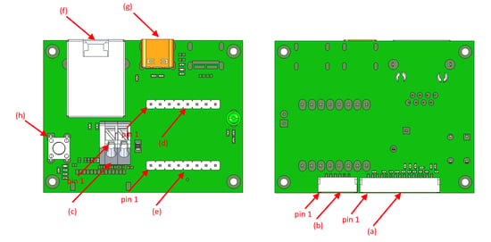
nano/mini-OEM and Helix Mesh Rider Radio – Eval Kit Connector Descriptions
Connectors

| S. No | Description |
|---|---|
| a | Primary connector to Helix Mesh Rider Radio |
| b | Power connector to Helix Mesh Rider Radio |
| c | Power connector, snap-in |
| d | Pin header, 2.54 mm (NOT POPULATED) |
| e | Pin header, 2.54 mm |
| f | RJ45 connector, ETH1 |
| g | USB-C Device data port |
| h | Factory reset switch |
Pin Headers
Power Connector (c)
| Pin Number | Voltage | Pin Description |
|---|---|---|
| PIN 1 | GND | GND |
| PIN 2 | +5.0V | Power In |
Pin header (d) (NOT POPULATED)
| Pin Number | Direction | Voltage | Pin Description |
|---|---|---|---|
| PIN 1 | GND | GND | |
| PIN 2 | I/O | Diff Signal | USB-Device-D- (Ethernet over USB only) |
| PIN 3 | I/O | Diff Signal | USB-Device-D+ (Ethernet over USB only) |
| PIN 4 | GND | GND | |
| PIN 5 | NOT USED | ||
| PIN 6 | GND | GND | |
| PIN 7 | NOT USED | ||
| PIN 8 | NOT USED |
Pin header (e)
| Pin Number | Direction | Voltage | Pin Description |
|---|---|---|---|
| PIN 1 | NOT USED | ||
| PIN 2 | NOT USED | ||
| PIN 3 | NOT USED | ||
| PIN 4 | NOT USED | ||
| PIN 5 | GND | GND | |
| PIN 6 | I/O | 0V to +2.8V | GPIO2 |
| PIN 7 | I | 0V to +3.3V | UART_RX |
| PIN 8 | O | 0V to +3.3V | UART_TX |
