
Doodle Labs 802.11ax (Wi-Fi 6) Industrial Wi-Fi Transceiver
Introduction:
Welcome to the world of Wi-Fi 6, with the Doodle Labs 802.11ax (Wi-Fi 6) Industrial Wi-Fi Transceiver! This setup guide for the 802.11ax (Wi-Fi 6) Mango Hardware Development Kit (HDK), designed to facilitate the development and testing of cutting-edge Wi-Fi 6 applications.
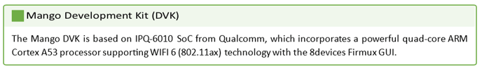
 Fig. 1. 802.11ax (Wi-Fi 6) Hardware Development Kit (HDK)
This comprehensive kit includes the Mango EVK CPU Board, a dedicated Doodle Labs 802.11ax Transceiver board, an 11ax adapter board, along with essential accessories such as a UART to USB adapter, Ethernet cable, and a power supply cable assembly tailored for both the Mango DVK and the 11ax Transceiver.
Whether you are working from a laptop or desktop equipped with Ubuntu, this guide will walk you through the detailed setup process, from hardware assembly to configuring communication ports. Our goal is to ensure a smooth configuration of both the Ethernet and serial connections, allowing you to jumpstart your project with ease and confidence.
System and Network Diagram(s):
802.11ax (Wi-Fi 6) Hardware Development Kit (HDK)
 Fig. 2. Individual 11ax Transceiver HDK System Diagram
 Fig. 3. AP Mode + Client Mode Wireless Network Diagram
Hardware and Equipment Setup:
802.11ax (Wi-Fi 6) Hardware Development Kit (HDK)
- Hardware Design Kit (HDK): HDK that includes CPU Board (8Devices Mango DVK), DUT board (11ax Transceiver), 11ax adapter board, UART to USB adapter, Ethernet cable, Power supply cable assembly for Mango DVK and 11ax Transceiver.
- Workstation: Laptop or Desktop with ubuntu
- Instrument: Regulated AC-DC Power supply.
- Connectors & Wires: Connection between Mango and PC is through UART to USB adapter (Optional- For debug / Fix MCS Rates, Network spatial stream, etc) & Ethernet cable.
 Fig. 4. Mango DVK Hardware
Hardware Setup & Preparation (Ethernet Port Configuration):
Begin by connecting the Mango EVK CPU Board and the 11ax Transceiver Device Under Test (DUT) board to the 11ax adapter board. Ensure all connections are secure and correctly aligned to avoid pin damage or incorrect readings.
- Connect ethernet cable provided from either of the two RJ45 ports shown below on the Mango DVK, to a PCs ethernet port
- 11ax Transceiver must be connected to Mango before the power on;
- 11ax Transceiver must have connected +5V power supply in order to start radios.
- Switch on the power supply (12V @1A max – For mango DVK, 5V @ 2A max for 11ax Transceiver).
- Once boot up is completed, press enter.
 Fig. 5. Configurable Ethernet Ports on the Mango DVK
Hardware Setup & Preparation (Serial Port Configuration):
Begin by connecting the Mango EVK CPU Board and the 11ax Transceiver Device Under Test (DUT) board to the 11ax adapter board. Ensure all connections are secure and correctly aligned to avoid pin damage or incorrect readings. For OS specific details, see the Windows Version or Ubuntu Version .
- Connect UART <-> USB serial converter to the header shown in a picture above (it depends on converter if 3V3 is required or no).
- 11ax Transceiver must be connected to Mango before the power on;
- 11ax Transceiver must have connected +5V power supply in order to start radios.
- Switch on the power supply (12V @1A max – For mango DVK, 5V @ 2A max for 11ax Transceiver).
- Open serial port using Putty (For Windows) / Terminal -> minicom for Ubuntu
- Speed: 115200, Tx flow control: OFF, Parity: None.
- Settings used to configure fixed modulation, network spatial stream etc.
- Once boot up is completed, press enter.
 Fig. 6. Serial Port Connection Details (UART)
Software and Network Setup:
Networking IP Address Configuration:
- Workstation Ethernet port IP: Setting it as 168.2.xxx is recommended.
- Set the Mango DVK IP to: 168.2.1 on one side and 192.168.2.2 on another side.
 Fig. 7. Example Static IP Addressing on Windows PC
Firmux Web GUI Configuration:
1. Open the browser and type 192.168.2.1/ 192.168.2.2 to start the webUI.
2. User name: root, Password: admin, Click on Login.
 Fig. 8. Firmux Web GUI Login Screen
3. Click on Wireless -> Networks and set the following parameters:
Mode : Access Point (AP) for first node setup / Station (STA) for any following nodes
SSID: (Your Network Name)
Network zone: Local Network
Security Mode and Password.
 Fig. 9. Firmux Wireless Network Settings
4. Click on the Radios Tab and set the following parameters:
Radio Type: Pineapple 2G (for 2.4GHz) / Pineapple 5G (for 5GHz) / Pineapple 6G (for 6GHz)
 Fig. 10. Select Radio Type (ie Pineapple 5G for 5GHz)
Channel Width: 20Mhz/40Mhz/80Mhz/160Mhz (For 2.4Ghz only 20Mhz and 40Mhz are available).
 Fig. 11. Select Radio Channel Width (Bandwidth)
Channel Selection: Auto / Any available frequency (refer to the figure below)
 Fig. 12. Select Radio Channel Automatically (Scan) or Manually
TxPower: Set the power from 7 dBm to 20 dBm
 Fig. 13. Select Radio Power or Tx Power (in dBm)
Click on the save option and then reboot the device to make sure the band change is reflected after the reboot.
 Fig. 14. Save the Selected Settings
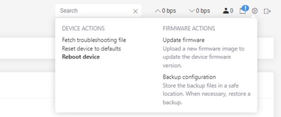
Fig. 15. Reboot the 802.11ax (Wi-Fi 6) Radio
5. Follow the above steps #1-4 on the other radio, and select it as Station (STA) on Step #3. After this on the AP node, we will be able to see the wireless client once the link is successful.
 Fig. 16. Confirm the New Wireless Client is Successful
6. Do an iperf test between the systems to verify the throughput.
Server iPerf3: 11AX Transceiver HDK
From PC/Workstation Terminal: SSH Root into 11AX Transceiver HDK and execute commands below.
-
ssh root@192.168.2.1 -
root@192.168.2.1's password: admin -
iperf3 -s
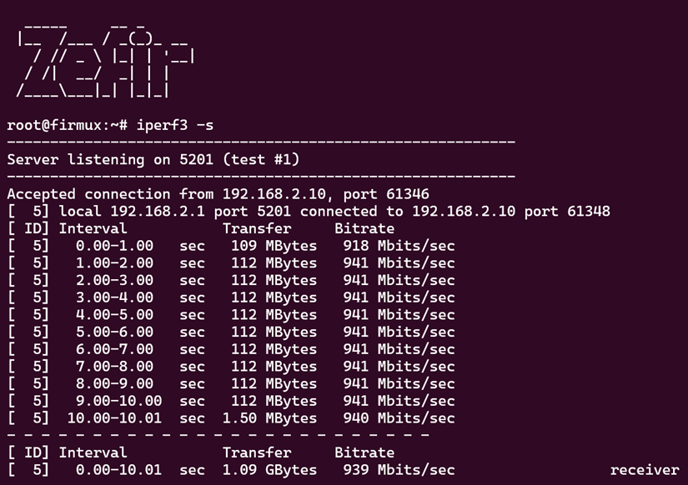
Fig. 17. Running iPerf3 Server on the 11AX Transceiver HDK
Client iPerf3: PC / Workstation
From PC/Workstation Terminal: Execute command below.
Iperf3 -c 192.168.2.1
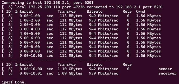
Fig. 18. Running iPerf3 Client on the PC / Workstation
Settings for Command Line 11AX Configuration:
Using iw dev commands offers a powerful way to configure and manage wireless network settings directly from the command line, enabling users to adjust parameters such as frequency, transmission power, and operating mode for network interfaces efficiently.
iw dev(To list all wireless interfaces, i.e. ath2)iw dev ath2(Shows the current state of the link, including signal strength, transmission rate, and other link-specific information).
Example results:
root@firmux:~# iw dev ath2 link

Connected to 44:1c:12:48:62:dd (on ath2)

       SSID: DoodleSATCOM

       freq: 5220

       RX: 2818051 bytes (21423 packets)

       TX: 44203 bytes (475 packets)

       signal: -51 dBm

       bss flags:     CTS-protection short-slot-time

       dtim period:   3

       beacon int:     100
iw dev ath2 info(Information about the ath2 interface, including its current operating frequency, channel width, and other wireless settings).
This will return results such as:
root@firmux:~# iw dev ath2 info

Interface ath2

       ifindex 21

       wdev 0x200000002

       addr 00:30:1a:50:73:50

       mld_addr 00:00:00:00:00:00

       ssid DoodleSATCOM

       type managed

       wiphy 2

       channel 44 (5220 MHz), width: 80 MHz, center1: 5210 MHz

       txpower 10.00 dBm

       4addr: on
iw dev ath2 scan(To scan for available wireless networks around ath2, which can be helpful to check for available networks or to troubleshoot connectivity issues)iw dev ath2 connect Network123(Connecting to an SSID named "Network123")iw dev ath2 disconnect Network123(Disconnecting to an SSID named "Network123")iw dev ath2 set freq 5180 40MHz(To set frequency to 5.18GHz + bandwidth to 40MHz)iw dev ath2 set channel 36 80MHz(To set channel to 36 + bandwidth to 80MHz)iw dev ath2 set txpower fixed 10(To set txpower to 10dBm)iw dev ath2 set power_save on(To enable power-saving features)iw dev ath2 set power_save off(To disable power-saving features)watch -n 1 iw dev ath2 info(This uses the watch command to repeatedly execute iw dev ath2 info every second, allowing you to see real-time changes to the network interface configuration).
Example output of command:
Every 1s: iw dev ath2 info                                   2024-04-20 07:18:54


Interface ath2

       ifindex 21

       wdev 0x200000002

       addr 00:30:1a:50:73:50

       mld_addr 00:00:00:00:00:00

       ssid DoodleSATCOM

       type managed

       wiphy 2

       channel 44 (5220 MHz), width: 80 MHz, center1: 5210 MHz

       txpower 10.00 dBm

       4addr: on
watch -n 1 "iw dev ath2 link | grep signal"(This uses the watch command to repeatedly execute iw dev ath2 link every second, while executing grep to only return the value of the signal). Example output of command:
Every 1s: iw dev ath2 link | grep signal                     2024-04-20 07:25:02


       signal: -52 dBm
Advanced Settings for Modulation Type and Network Spatial Streams:
To fix the data rate (Modulation type) and NSS (Network spatial stream), type the following commands in the serial port (refer to the last page).
Cfg80211tool ath2 nss 1(To set the Number of spatial streams)Cfg80211tool ath2 he_mcs 0(To set MCS rate)
Serial UART PC Preparation (Windows Version)
Preferred version of OS: Windows 10/11
Install the following software’s in the windows PC.
- Putty (For Serial Communication to the DUT)
- Download Putty here: https://www.putty.org/
- Install Putty onto your PC.
- Connect UART <-> USB converter to your PC.
- Type Device manager in search.
- Press on Ports (COM & LPT).
- Check which COM port is for UART <-> USB converter.
 Fig. 19. Checking Device Manager to Discover USB Serial Port (COM4)
g. Next open a new Putty terminal and press Serial.
 Fig. 20. Opening Putty Terminal and Enabling Serial
h. Type in Serial line COM port to which connected UART <-> USB converter. For example: COM4. Type in Speed: 115200.
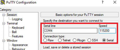
Fig. 21. Inputting the Serial Line (i.e. COM4) and Speed (i.e. 115200)
i. Press the Open button at the bottom-right of the screen to begin UART connection
Serial UART PC Preparation (Ubuntu Version)
Preferred version of OS: Ubuntu 22.04+
In the Ubuntu PC, Open A New Terminal:
1. In Command Line open up the dev (or device) directory
-
ls /dev
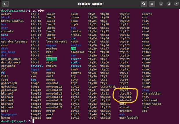
Fig. 22. Command Line Check the /dev Directory for ttyUSB0 or ttyUSB1
2. To check the serial port (Refer the above figure)
-
sudo minicom -s
a. Enter the sudo user PC / Workstation password.
 Fig. 23. Utilize the minicom Ubuntu/Linux Utility
3. Select the Serial port setup option in the minicom dropdown menu.
 Fig. 24. Select the Serial Port Setup Option
4. Set the data rate and port details and enter. After that you will be able to enter serial port UART access.
 Fig. 25. Set up the Data Rate and Port Details
5. Press Enter to go inside the debug port.
 Fig. 26. Initiate Serial (UART) Debug